

Original Feishu Document · Source Revision 34
💡
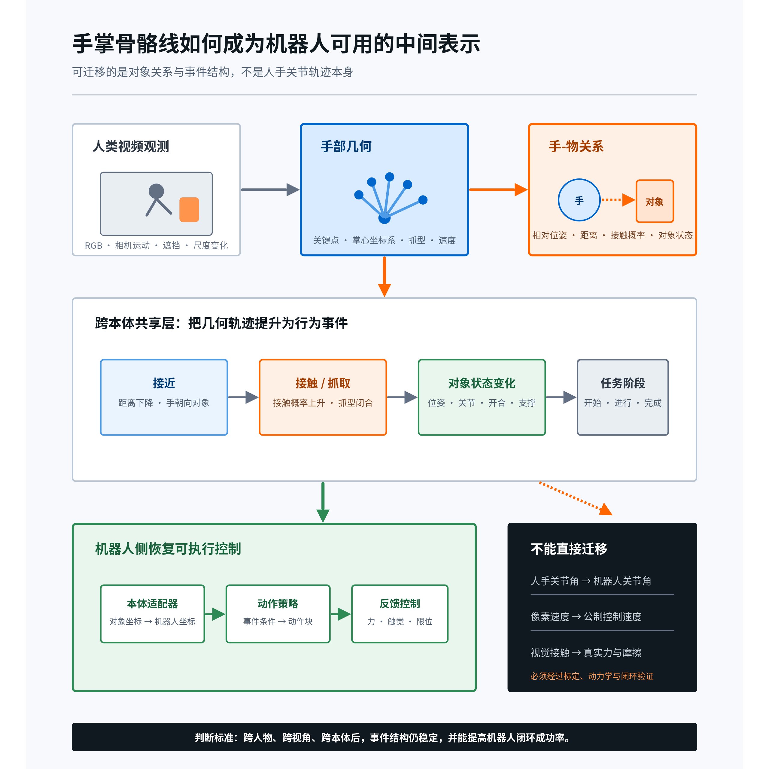
Key takeaway: Palm skeletal lines are not robot action labels. They are an intermediate geometric representation recovered from human videos that captures where the hand is, how it is oriented, what grasp type it uses, and which object it is approaching. The variables truly suitable for transfer between humans and robots are the hand-object relative pose in the object coordinate frame, contact events, object state changes, and task phases.
1. Why Palm Skeletal Lines Are Needed
With RGB video alone, the model observes only pixel changes. A hand skeleton compresses high-dimensional appearance into a set of keypoints with anatomical topology, making motion easier to compare across people, skin tones, lighting conditions, and backgrounds.
| Level | Representative Signals | Questions It Can Answer | Questions It Cannot Directly Answer |
|---|---|---|---|
| Pixels | RGB, optical flow, feature maps | Where changes occur in the image | Whether the changes are caused by the hand, camera, or occlusion |
| Hand skeleton | 2D/3D keypoints, confidence | Palm position, orientation, fingertip opening, motion trend | Actual force, friction, stable contact, robot joint commands |
| Hand-object relationship | Relative pose, distance, contact probability, object state | How the hand acts on the object and which phase the action is in | Absolute ground-truth dynamics without calibration |
| Robot control | q, dq, end-effector pose, torque, tactile sensing | What the robot should execute next | Cannot be determined directly from the human hand skeleton alone |
Key boundary: A skeleton is the structured post-processing result of visual observations. It may come from a pretrained model or offline annotation; this does not mean that the original human video initially includes joint velocities, contact forces, or robot actions.
2. The 21-Keypoint Hand Skeleton and Bone Connections
One of the most commonly used engineering representations is the 21-keypoint topology from MediaPipe Hands. Keypoint 0 is the wrist; 1–4 are the thumb; 5–8 are the index finger; 9–12 are the middle finger; 13–16 are the ring finger; and 17–20 are the little finger.
| Region | Keypoints | Typical Connections | Primary Uses |
|---|---|---|---|
| Palm base | 0, 5, 9, 13, 17 | 0-5, 5-9, 9-13, 13-17, 17-0 | Palm center, scale, plane, and orientation |
| Thumb | 1, 2, 3, 4 | 0-1-2-3-4 | Opposition, pinching, and grasp-type discrimination |
| Index finger | 5, 6, 7, 8 | 0-5-6-7-8 | Pointing, pressing, and pinching |
| Middle finger | 9, 10, 11, 12 | 0-9-10-11-12 | Palm length, principal direction, and enveloping grasp |
| Ring finger | 13, 14, 15, 16 | 0-13-14-15-16 | Grasp type and degree of enclosure |
| Little finger | 17, 18, 19, 20 | 0-17-18-19-20 | Palm width, lateral grasping, and degree of enclosure |
Each observed point should store not only its coordinates but also its confidence: . Here, may be estimated depth in the camera coordinate frame or merely relative depth; the two must not be used interchangeably.
Interpretation: Hand keypoint h with index j in frame t is jointly represented by its 3D position coordinates x, y, and z and keypoint confidence c. Here, z can be interpreted as actual depth only after camera calibration or scale recovery.
3. Palm Coordinate Frame: From Keypoints to Transferable Geometry
Directly feeding all 21 points into a model can work, but it transfers poorly across viewpoints and morphologies. A more robust approach is to construct a local palm coordinate frame first.
Let the wrist be , the index-finger metacarpophalangeal joint be , the middle-finger metacarpophalangeal joint be , and the little-finger metacarpophalangeal joint be :
Interpretation: p with subscripts 0, 5, 9, and 17 denotes the positions of the wrist, index-finger metacarpophalangeal joint, middle-finger metacarpophalangeal joint, and little-finger metacarpophalangeal joint, respectively. These four points are subsequently used to establish the local palm coordinate frame.
Interpretation: Define the origin o_h of the palm coordinate frame at wrist keypoint p_0.
Derivation: Choose hand keypoint p0 as the wrist or palm-base origin, then translate points in the image/world coordinate frame to this origin to define the origin of the local hand reference frame.
Interpretation: Use the vector from the little-finger metacarpophalangeal joint to the index-finger metacarpophalangeal joint to define the palm’s lateral axis e_x, and divide it by its length to normalize it into a unit vector.
Derivation: Use the line connecting palm points p5 and p17 as the lateral axis, then divide it by its L2 norm to obtain a unit vector, ensuring that the directional feature is invariant to palm scale.
Interpretation: First, use the direction from the wrist to the middle-finger metacarpophalangeal joint to obtain a provisional longitudinal axis. Next, take the cross product of the lateral axis and the provisional longitudinal axis to obtain the palm normal e_z. Finally, take another cross product to obtain the longitudinal axis e_y, which is orthogonal to the other two axes.
Derivation: First normalize the direction from p9 to p0 as a provisional y-axis. Then use a cross product to construct and normalize a z-axis orthogonal to the x-axis. Finally, compute z cross x to obtain a strictly orthogonal y-axis.
The palm pose can then be written as , where . If the object pose is , the more suitable quantity to learn is:
Interpretation: The palm pose T_h consists of the rotation matrix R_h and position o_h. The three columns of the rotation matrix are the x, y, and z unit axes of the local palm coordinate frame, respectively. T_o denotes the object pose in the same reference coordinate frame.
Interpretation: The object-to-palm relative pose is obtained by first applying the inverse object pose to transform into the object coordinate frame and then applying the palm pose. The result describes “where the palm is and how it is oriented from the object’s perspective.”
Derivation: Homogeneous transforms are multiplied along the transformation path. To go from the object coordinates to the hand coordinates, first apply the inverse object transform and then the hand transform; therefore, the relative transform is the inverse of T_o multiplied by T_h.
It describes “where the hand is relative to the cup, drawer, or tool,” which is closer to the task’s causal structure than “which pixel in the camera image contains the hand.”
💡
When keypoints are nearly collinear, the palm is viewed edge-on by the camera, or severe occlusion occurs, the normal becomes unstable. Training data must retain both visibility and coordinate-frame confidence, and low-confidence frames must be downweighted or interpolated.
4. Finger Flexion, Grasp Type, and Motion Estimation
4.1 Flexion Angles and Grasp Types
For three consecutive points on a finger, the joint angle can be written as:
Interpretation: With joint point b as the vertex, construct two bone vectors from b toward a and c. Divide the dot product of the two vectors by the product of their lengths, then take the arccosine to obtain the joint angle θ.
Derivation: The angle between two vectors is given by the arccosine of their normalized dot product. a-b and c-b are the two edges with b as the vertex, and dividing the dot product by the lengths of the two edges removes scale.
Combining the flexion angles of all five fingers, the distances between the thumb and each fingertip, and fingertip spacing normalized by palm width makes it possible to identify grasp types such as pinch, power grasp, open palm, and pointing. Grasp type should be treated as a probability distribution rather than a hard label, for example .
Interpretation: p(g_t∣H_{1:t}) denotes the conditional probability that the current grasp type g_t belongs to each candidate grasp type, given the observed hand history H from frame 1 through frame t.
4.2 Estimating Velocity from Position Sequences
The velocity of a 2D keypoint is a post-processed estimate:
Interpretation: The 2D velocity of keypoint j in frame t is estimated using a central difference: divide the difference between its pixel positions in the future frame t+k and past frame t−k by the total elapsed time 2kΔt between the two frames.
Derivation: The central difference divides the displacement between two symmetric samples at t+k and t-k by the total time interval 2k delta t, producing lower truncation error than a one-sided difference.
To reduce the effects of differences in palm size and camera distance, the velocity can be normalized by palm width :
Interpretation: s_t is the palm width in pixels in frame t, equal to the 2D Euclidean distance between the metacarpophalangeal joints of the index and little fingers. It serves as a normalization reference for subject scale and camera distance.
Interpretation: The normalized velocity equals the 2D pixel displacement divided by the time interval and current palm width. It indicates how many palm widths the keypoint moves per unit time, rather than how many meters it moves.
Derivation: Further dividing the 2D velocity by scale s_t converts pixel-per-frame changes into motion relative to hand scale, making samples from different distances and different hand sizes more comparable.
This represents “how many palm widths are traversed per second,” not meters per second. Three-dimensional velocity in the camera coordinate frame can be estimated only when camera intrinsics, depth, multiple views, or a reliable 3D hand model are available:
Interpretation: Three-dimensional velocity also uses a central difference: divide the difference between estimated 3D positions at future and past time points by the total elapsed time. The result can be interpreted as meters per second only when the 3D positions have a reliable metric scale.
Derivation: Apply the same central difference to the reconstructed 3D point p_hat to obtain a velocity estimate in physical spatial units, provided that the depth and coordinate frame have been calibrated.
In a practical pipeline, trajectories should be smoothed before differentiation, and velocity uncertainty should be reported as well. When camera motion is significant, camera ego-motion must first be estimated and removed.
5. From Hand Skeletons to Hand-Object Interaction Graphs
What a robot truly needs to learn is not an isolated hand, but the relationships among the hand, objects, environment, and events. Each frame can be represented as a dynamic graph:
Interpretation: The interaction graph G_t for frame t consists of three types of nodes and three types of edges: hand nodes, object nodes, environment nodes, intra-hand skeletal edges, hand-to-object interaction edges, and object-to-environment relation edges.
Derivation: Place hand nodes, object nodes, and environment nodes into three respective vertex sets, then combine hand-hand, hand-object, and object-environment relationships into an edge set to obtain a heterogeneous interaction graph.
| Graph Element | Example Features | Semantics |
|---|---|---|
| Hand node | Palm pose, fingertip positions, flexion angles, velocity, confidence | Agent state |
| Object node | Category, 6D pose, dimensions, articulated parts, state | Manipulated object |
| Environment node | Tabletop, container, support surface, obstacle | Constraints and context |
| Hand-hand edge | Skeletal connections, relative angles | Anatomical topology |
| Hand-object edge | Distance, relative pose, approach velocity, contact probability | Interaction relationship |
| Object-environment edge | Support, containment, articulation, collision relationships | Physical constraints on object state changes |
An interpretable contact probability model can be written as:
Interpretation: In frame t, the probability that hand point i contacts object o is obtained by using a sigmoid function to map a set of evidence to the range from 0 to 1. A shorter distance, a stronger approach trend, and greater consistency with the object’s state change generally imply a higher contact probability; φ_t denotes other contextual features.
Derivation: Use a sigmoid function to map a linear combination of distance, approach velocity, object state change, and contextual features to the range from 0 to 1, yielding a probabilistic model of contact occurrence.
Here, is the distance from the fingertip to the object surface, is the approach velocity, is the object state change, and represents context such as occlusion, viewpoint, and detection confidence. This quantity remains a contact probability based on visual evidence and is not equivalent to actual contact force.
6. Choosing Among 2D Skeletons, 3D Skeletons, MANO, and Multi-View Representations
| Representation | Advantages | Main Drawbacks | Recommended Uses |
|---|---|---|---|
| 2D 21-keypoint skeleton | Inexpensive, stable, and scalable | Severe depth and occlusion ambiguities | Coarse screening, action phases, and 2D trajectories |
| Monocular 3D keypoints | Provide relative 3D structure | Scale, rotation, and occlusion errors | Representation pretraining and relative motion |
| MANO parameters | Continuous hand shape and pose, convenient for rendering | High fitting cost and significant model bias | High-value clips, synthetic augmentation, and geometric consistency |
| Multi-view 3D | Higher accuracy and observability | High acquisition and calibration costs | Gold-standard datasets, evaluation sets, and contact research |
| Egocentric + hand-object | Close to the robot viewpoint and rich in task information | Severe occlusion; hands often leave the frame | Manipulation policy pretraining |
A scalable solution should not use only one representation. A tiered data structure is recommended: “massive-scale 2D/weak 3D + medium-scale MANO/object trajectories + small-scale multi-view and force/tactile gold-standard data.”
7. Public Papers and Datasets
- MediaPipe Hands: Real-time monocular hand keypoint detection and a commonly used engineering baseline for the 21-keypoint topology.
- HaMeR: Recovers 3D hand meshes from images and is suitable for MANO or mesh estimation on high-value clips.
- WiLoR: 3D hand reconstruction for in-the-wild images, emphasizing large-scale and complex scenes.
- ARCTIC: 3D interaction data involving two hands and articulated objects, suitable for studying contact and object state.
- HOT3D: Egocentric 3D hand-object data containing spatiotemporal relationships between hands and objects.
- EgoDex: An egocentric human dataset and learning framework for dexterous manipulation.
- EgoMimic: Learns manipulation behaviors from egocentric human videos and robot data.
- DexImit: Focuses on representations and transfer from human dexterous manipulation to robot imitation.
When reviewing these works, verify: whether keypoints are manually annotated ground truth, motion-capture ground truth, or model-generated pseudo-labels; whether object poses are calibrated; whether contact is defined by a geometric threshold or measured by sensors; and whether velocity has metric scale.
8. Recommendations for the Behavior Prompt / Tokenizer
It is not advisable to quantize the coordinates of all 21 points individually and use them directly as behavior tokens. A hierarchical tokenizer is more appropriate:
- Phase tokens: reach, pre-grasp, contact, manipulate, release, retract.
- Relationship tokens: Direction, distance interval, orientation, and approach or retreat trend of the hand relative to the object.
- Grasp-type tokens: Probabilistic encoding of pinch, power grasp, support, push, pull, and other grasp types.
- Local geometry tokens: Continuous residuals for palm pose, fingertip layout, and flexion angles.
- Event tokens: Initial contact, object motion onset, articulation state change, and release.
- Uncertainty tokens: Occlusion, low confidence, unknown scale, and strong camera motion.
The training objective can be written as:
Interpretation: The total training loss L is a weighted sum of five sub-objectives: geometric reconstruction, future prediction, alignment between human and robot representations, interaction event recognition, and robot action supervision. Each λ controls the relative weight of its corresponding loss in the overall objective.
Derivation: Multi-task training combines the losses for reconstruction, next-state prediction, cross-modal alignment, event detection, and robot supervision using a weighted sum. Each lambda controls the relative contribution of the corresponding evidence to the total gradient.
- : Reconstruct local hand-object geometry to prevent the tokens from losing critical details.
- : Predict future relationships, grasp types, and object states to learn dynamical trends.
- : Align shared semantics between human videos and robot trajectories.
- : Supervise event boundaries such as contact, movement, and release.
- : Supervise executable actions or action chunks only on robot data.
In this way, human data primarily shapes the shared conditional behavior distribution and event structure, while robot data maps the shared semantics into the control space of a specific embodiment.
9. Boundaries of Transfer to Robots
| Transferable | Requires Adaptation | Not Directly Transferable |
|---|---|---|
| Approach direction, object-center trajectory, grasp phase, object state changes | Palm scale, degrees of freedom, grasp type, workspace, velocity range | Pointwise mapping from human hand keypoints to robot qpos |
| Bimanual coordination relationships, tool-object relationships, contact timing | Camera viewpoint, control frequency, latency, compliance | Inferring actual torque and friction coefficients from visual skeletons |
| Causal event chains before and after success | Object materials and dynamics, end-effector morphology | Treating monocularly estimated meters per second as ground-truth control velocity |
10. Minimum Viable Experiment
10.1 Data
- Select three task categories: grasping a cup, opening a drawer, and picking up a tool. Each category should include successful, failed, and recovery clips.
- For human videos, output the 21-keypoint skeleton, object mask or pose, camera motion, contact probability, task phase, and confidence.
- Robot data should additionally include end-effector pose, gripper state, q/dq, torque or tactile sensing, and success labels.
10.2 Control Groups
- RGB-only video pretraining.
- RGB + hand skeleton.
- RGB + hand skeleton + object trajectory.
- RGB + complete hand-object interaction graph + event tokens.
10.3 Decisive Metrics
- Contact-event F1, object-state prediction accuracy, and future relative-trajectory error on human videos.
- Task success rate after few-shot robot fine-tuning, number of required robot trajectories, and generalization to unseen objects.
- Robustness to occlusion, camera motion, handedness, and different hand shapes.
- Failure categories: missed grasp, post-contact slip, pose mismatch, object not moving, control latency, and recovery failure.
✅
Go/No-Go criterion: A “hand-object interaction representation” can be considered to have learned transferable behavior structure, rather than merely stronger visual fitting, only if it consistently improves real-robot success rates over RGB-only and skeleton-only baselines under the same robot-data budget, and the gains persist for unseen objects or unseen operators.
11. Final Assessment
Palm skeletal lines are worth generating at scale, but their proper role is as an intermediate observation layer, not the final action layer. The most valuable training unit is not “how many pixels fingertip 8 moved,” but rather “which hand approached which object, using what grasp type, from which direction, under how much uncertainty, and what observable state change it caused.”
Therefore, the data pipeline should advance from hand-centric representations to object-centric hand-object interaction representations, followed by embodiment grounding using a small amount of high-quality robot data.